Kubernetes Networking Fundamentals
-
 Nived Velayudhan
- Dev ops, Kubernetes, Open shift
- March 13, 2022
The Kubernetes Network Model specifies:
- Every Pod gets its own IP address. There should be no need to create links between pods and no need to map container ports to host ports.
- Pods on a node can communicate with all pods on all nodes without NAT .
- Agents on a node ( eg. system daemons, Kubelet ) can communicate with all the pods in that node.
- Containers within a Pod share their network namespace ( IP and MAC address ) and therefore can communicate with each other using the loopback address.
Kubernetes networking addresses four concerns:
- Container-to-Container Networking
- Pod-to-Pod Networking
- Pod-to-Service Networking
- Internet-to-Service Networking
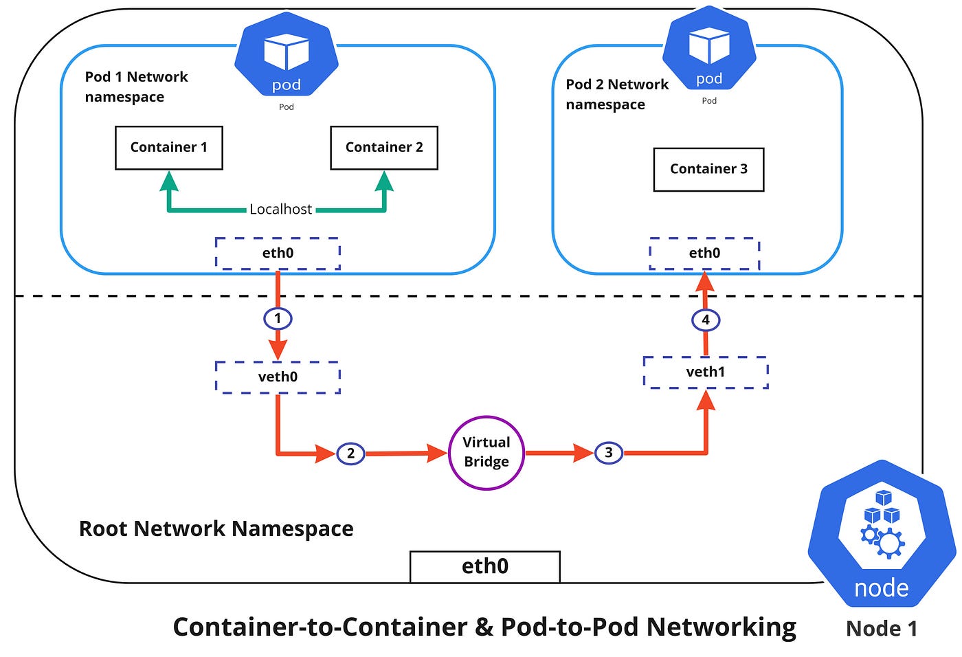
Container-to-Container Networking
Container-to-Container networking happens through the Pod network namespace. Network namespaces allow us to have separate network interfaces and routing tables that are isolated from the rest of the system and can operate independently. Every Pod will have its own network namespace and containers inside that Pod share the same IP address and ports. All communication between these containers would happen via the localhost as they are all part of the same namespace. ( Represented by the green line in the diagram )
Pod-to-Pod Networking
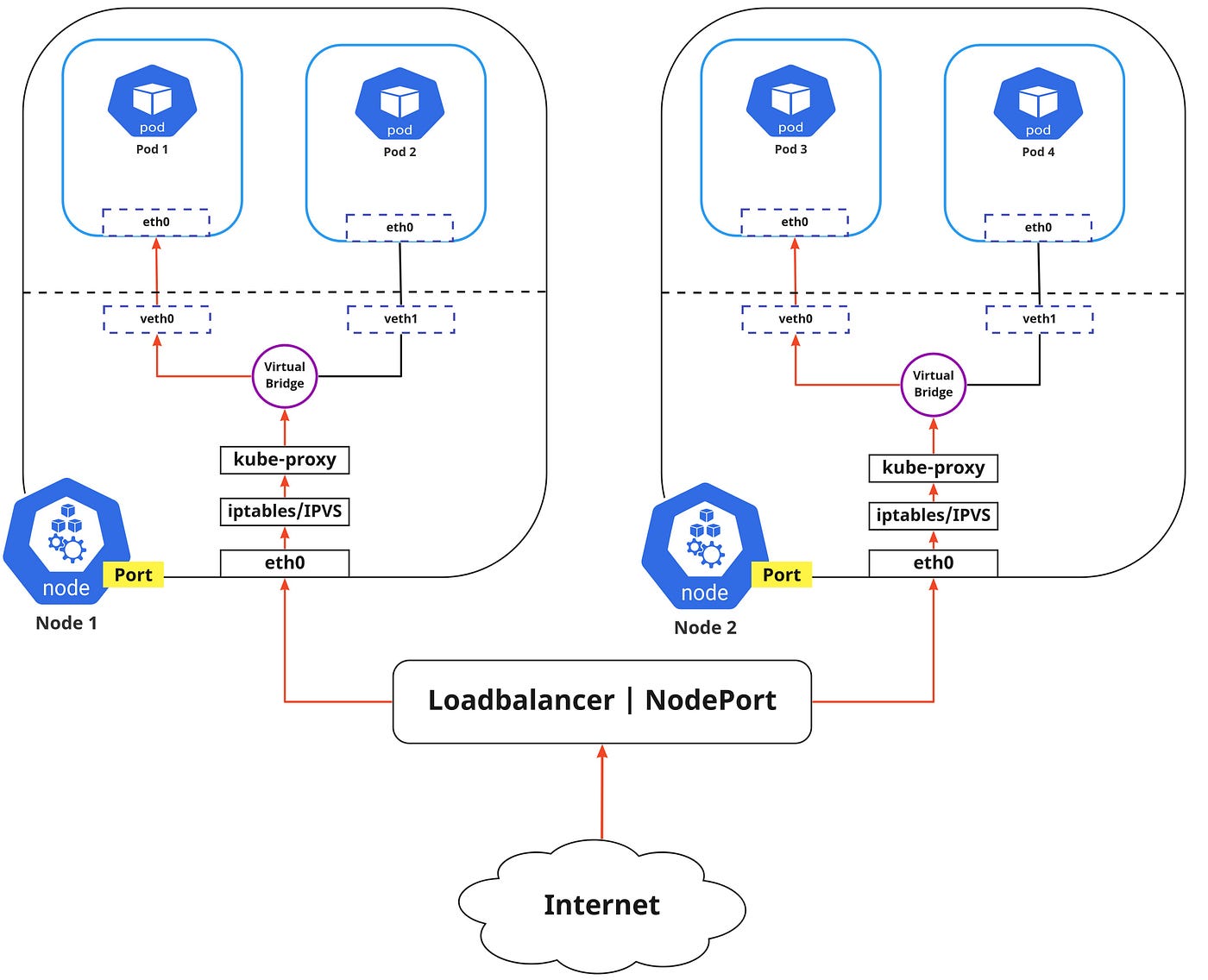
In Kubernetes, every node has a designated CIDR range of IPs for Pods. This would ensure that every Pod gets a unique IP address that can be seen by other Pods in the cluster and also ensures that when a new Pod is created, the IP address never overlaps. Unlike Container-to-Container networking, Pod-to-Pod communication happens using real IPs, whether the Pod is deployed on the same node or a different node in the cluster.
You can notice from the diagram above that, for Pods to communicate with each other, the traffic has to flow between the Pod network namespace and the Root network namespace. This is achieved by connecting both the Pod namespace and the root namespace by a virtual ethernet device or a veth pair (veth0 to Pod namespace 1 and veth1 to Pod namespace 2 in the diagram). Both these virtual interfaces would be connected via a virtual network bridge which will then allow traffic to flow between them using the ARP protocol.
So if data is sent from Pod 1 to Pod 2, the flow of events would like this ( refer to diagram above )
- Pod 1 traffic flows through eth0 to the root network namespaces virtual interface veth0.
- Then traffic goes via veth0 to the virtual bridge which is connected to veth1.
- Traffic goes via the virtual bridge to veth1.
- Finally, traffic reaches eth0 interface of Pod 2 via veth1.
Pod-to-Service Networking
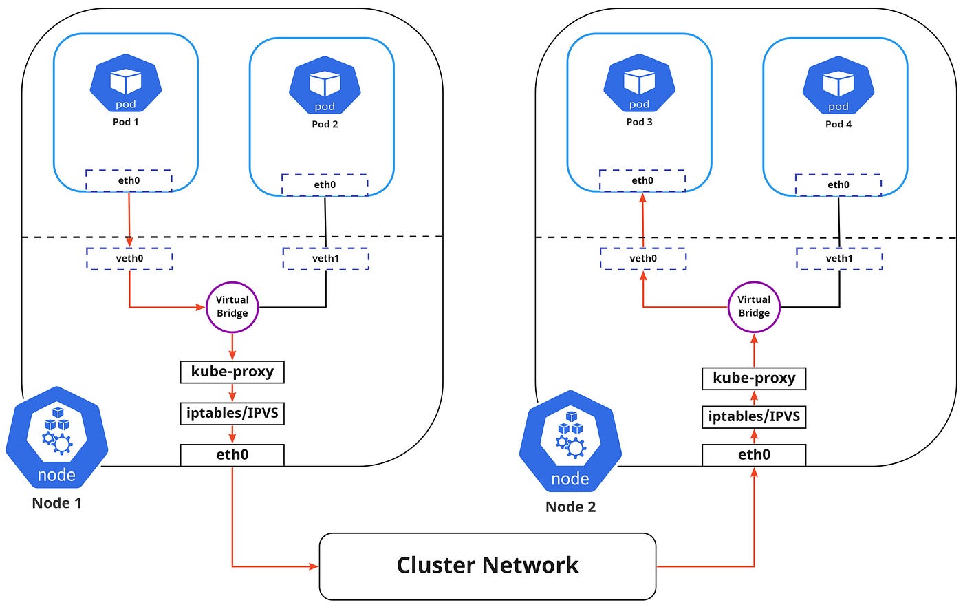
Pods are very dynamic in nature. They may need to scale up or down based on demand. They may be created again in case of an application crash or a node failure. All of these events cause the Pods IP address to change and this makes networking a challenge.
Kubernetes solves this problem by using Service. So what exactly is the service responsible for?
- Assigning a static virtual IP address in the frontend that would be used to connect any backend Pods that are associated with the Service.
- Load-balancing any traffic that is addressed to this virtual IP to the set of backing Pods.
- Keeping a track of the IP address of the Pods, so even if the Pod IP address changes, the clients wouldn’t have any trouble connecting to the Pod as they only directly connect with the static virtual IP address of the Service itself.
The in-cluster load balancing can be done in two ways:
- IPTABLES: In this mode, kube-proxy watches for changes in the API Server, and for each new service, it installs iptables rules, which capture traffic to the Service’s clusterIP and port and this would redirect that traffic to the backend Pod for this Service. The Pod is selected randomly. This mode is more reliable and has a lower system overhead because traffic is handled by Linux Netfilter without the need to switch between userspace and the kernel space. ( Refer — iptables proxy mode )
- IPVS: IPVS is built on top of the Netfilter and implements transport-layer load balancing. IPVS uses the netfilter hook function using the hash table as the underlying data structure and works in the kernel space. This means that kube-proxy in IPVS mode will redirect traffic with lower latency, higher throughput, and much better performance compared to kube-proxy in iptables mode. ( Refer — IPVS proxy mode )
I found an interesting read comparing kube-proxy modes here — iptables vs ipvs
The flow of the package from Pod 1 to Pod 3 via a service to a different node is shown in the diagram above ( marked in red ). Please note that the package traveling to the virtual bridge would have to route it via the default route (eth0) as the ARP protocol running on the bridge wouldn’t understand the Service and later they to be filtered by iptables which in turn would use the rules defined in the node by kube-proxy. Therefore the diagram directly shows the path as it is.
Internet-to-Service Networking
So far we have discussed how traffic is routed within the cluster. Now if we need to expose an application to the external network, we could do that in two ways:
- Egress : This is when you want to route traffic from your Kubernetes Service out to the Internet. In this, iptables would perform the source NAT so the traffic would appear to be coming from the node and not the pod.
- Ingress : This is the incoming traffic to services coming from the external world. Ingress also allows and blocks particular communications with services using a set of rules for connections. Typically, there are two ingress solutions that function on different network stack regions: the service load balancer and the ingress controller.
Discovering services:
There are two ways in which Kubernetes can discover a Service:
- Environment Variables : The kubelet service running on the node where your Pod runs are responsible for setting up environment variables for each active service in the format {SVCNAME}_SERVICE_HOST & {SVCNAME}_SERVICE_PORT. Do note that you must create the Service before the client Pods come into existence. Otherwise, those client Pods won’t have their environment variables populated.
- DNS : The DNS service is implemented as a Kubernetes service that maps to one or more DNS server pods which are scheduled just like any other pod. Pods in the cluster are configured to use the DNS service, with a DNS search list that includes the pod’s own namespace and the cluster’s default domain. A cluster-aware DNS server, such as CoreDNS, watches the Kubernetes API for new Services and creates a set of DNS records for each one. If DNS has been enabled throughout your cluster then all Pods should automatically be able to resolve Services by their DNS name. The Kubernetes DNS server is the only way to access ExternalName Services. ( Refer — DNS for Services and Pods )
ServiceTypes for Publishing Services:
Kubernetes Services provide us with a way of accessing a group of Pods which may usually be defined by using a label selector. This could be applications trying to access other applications within the cluster or it could also allow us to expose an application running in the cluster to the external world. Kubernetes ServiceTypes allow you to specify what kind of Service you want.
- ClusterIP : This is the default ServiceType. This makes the Service only reachable from within the cluster and allows applications within the cluster to communicate with each other. There is no external access.
- LoadBalancer : This ServiceType exposes the Services externally using the cloud provider’s load balancer. Traffic from the external load balancer is directed at the backend Pods. The cloud provider decides how it is load-balanced.
- NodePort : This allows the external traffic to access the Service by opening a specific port on all the nodes. Any traffic that is sent to this Port is then forwarded to the Service.
- ExternalName : This type of Service maps a Service to a DNS name by using the contents of the externalName field by returning a CNAME record with its value. No proxying of any kind is set up.
This article was originally published in [medium](https://medium.com/techbeatly/kubernetes-networking-fundamentals-d30baf8a28c8) .
Nived Velayudhan
I help businesses solve their IT challenges in Linux Infrastructure such as automation and containerization on hybrid cloud environments by using customized open source solutions.
Note
Disclaimer: The views expressed and the content shared in all published articles on this website are solely those of the respective authors, and they do not necessarily reflect the views of the author’s employer or the platform. We strive to ensure the accuracy and validity of the content published on our website. However, we cannot guarantee the absolute correctness or completeness of the information provided. It is the responsibility of the readers and users of this website to verify the accuracy and appropriateness of any information or opinions expressed within the articles. If you come across any content that you believe to be incorrect or invalid, please contact us immediately so that we can address the issue promptly.